Optimizing a Wing Inside a Fluid Simulation
(My last post in a series about human flight; post 1, post 2).
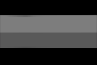
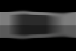
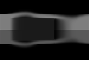
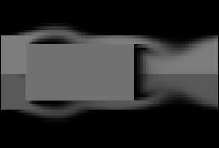
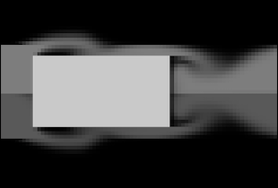
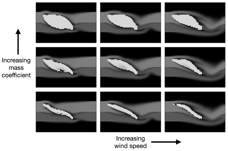
[The images above are videos. Click to pause or play.]
Legos are an excellent meta-toy in that they represent the potential for a near-infinite number of toys depending on how you assemble them. Each brick has structure. But each brick is only interesting to the extent that it can combine with other bricks, forming new and more complex structures. So in order to enjoy Legos, you have to figure out how they fit together and come up with a clever way of making the particular toy you have in mind. Once you have mastered a few simple rules, the open-ended design of Lego bricks lets you build anything you can imagine.
Our universe has the same versatile structure. It seems to run according to just a few simple forces, but as those forces interact, they give rise to intricate patterns across many scales of space and time. You see this everywhere you look in nature – in the fractal design of a seashell or the intricate polities of a coral. In the convection of a teacup or the circulation of the atmosphere. And this simple structure even determines the shape and behavior of man’s most complicated flying machines.
To see this more clearly, we are going to start from the basic physical laws of airflow and use them to derive the shape of a wing.1 Since we are using so few assumptions, the wing shape we come up with will be as fundamental as the physics of the air that swirls around it. This is pretty fundamental. In fact, if an alien species started building flying machines on another planet, they would probably converge on a similar shape.
Navier-Stokes
We will begin this journey with the Navier-Stokes equation, which sums up pretty much everything we know about fluid dynamics. It describes how tiny fluid parcels interact with their neighbors. The process of solving fluid dynamics problems comes down to writing out this equation and then deciding which terms we can safely ignore. In our case, we would like to simulate the flow of air through a wind tunnel and then use it to evaluate various wing shapes.
Since the pressure differences across a wind tunnel are small, one of the first assumptions we can make is that air is incompressible. This lets us use the incompressible form of the Navier-Stokes equation:
\(\underbrace{\frac{\partial \mathbf{u}}{\partial t}}_{\text{velocity update}} ~=~ - \underbrace{(\mathbf{u} \cdot \nabla)\mathbf{u}}_{\text{self-advection}} ~+~ \underbrace{\nu \nabla^2 \mathbf{u}}_{\text{viscous diffusion}} \\ ~+~ \underbrace{f}_{\text{velocity $\uparrow$ due to forces}}\) \(\underbrace{\frac{\partial \mathbf{u}}{\partial t}}_{\text{velocity update}} ~=~ - \underbrace{(\mathbf{u} \cdot \nabla)\mathbf{u}}_{\text{self-advection}} ~+~ \underbrace{\nu \nabla^2 \mathbf{u}}_{\text{viscous diffusion}} ~+~ \underbrace{f}_{\text{velocity $\uparrow$ due to forces}}\)
Another term we can ignore is viscous diffusion. Viscous diffusion describes how fluid parcels distribute their momenta due to sticky interactions with their neighbors. We would say that a fluid with high viscosity is “thick”: common examples include molasses and motor oil. Even though air is much thinner, viscous interactions still cause a layer of slow-moving air to form along the surface of an airplane wing. However, we can ignore this boundary layer because its contribution to the aerodynamics of the wing is small compared to that of self-advection.
The final term we can ignore is the forces term, as there will be no forces on the air once it enters the wind tunnel. And so we are left with but a hair of the original Navier-Stokes hairball:
\[\underbrace{\frac{\partial \mathbf{u}}{\partial t}}_{\text{velocity update}} = \underbrace{- (\mathbf{u} \cdot \nabla)\mathbf{u}}_{\text{self-advection ("velocity follows itself")}}\]This simple expression describes the effects that really dominate wind tunnel physics. It says, intuitively, that “the change in velocity over time is due to the fact that velocity follows itself.” So the entire simulation comes down to two simple rules:
-
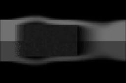
Rule 1: Velocity follows itself (+)
-
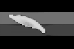
Rule 2: Volume is conserved (+)
By alternating between these two rules, we can iteratively 1) move the system forward in time and 2) enforce conservation of volume and mass. In practice, we implement each rule as a separate function and then apply both functions to the system at every time step. This allows us to simulate, say, a gust of wind passing through the wind tunnel. But before we can direct this wind over a wing, we need to decide how to represent the wing itself.
Representing the Wing
Choosing an Objective
Now we are at the point where we can simulate how air flows over arbitrary, semi-permeable shapes. But in order to determine which of these shapes makes a better wing, we still need to define a measure of performance. There are many qualities that one could look for in a good wing, but we will begin with the most obvious: it should convert horizontal air velocity into upward force as efficiently as possible. We can measure this ability using something called the lift-drag ratio where “lift” measures the upward force generated by the wing and “drag” measures the frictional forces between the air and the wing. Since “change in downward airflow” in the tunnel is proportional to the upward force on the wing, we can use it as a proxy for lift. Likewise, “change in rightward airflow” is a good proxy for the drag forces on the wing. With this in mind, we can write out the objective function as
\[\max_{\theta} L/D\]where \(\theta\) represents some tunable parameters associated with the shape of the wing mask and \(L/D\) can be obtained using the initial and final wind velocities of the simulation according to
\[\begin{align} L/D &= \frac{\text{lift}}{\text{drag}}\\ &= \frac{\text{change in downward airflow}}{-\text{change in rightward airflow}}\\ &= \frac{ -\big ( v_y(t)-v_y(0) \big )}{-\big ( v_x(t)-v_x(0) \big )}\\ &= \frac{ v_y(t)-v_y(0) }{ v_x(t)-v_x(0)} \end{align}\]Solving this optimization problem will give us a wing shape that generates the most efficient lift possible. In other words, we new have the correct problem setup; what remains is to figure out how to solve it.
Optimization
So let’s review. Our goal is to simulate a wind tunnel and use it to derive a wing shape. We began by writing down the general Navier-Stokes equation and eliminating irrelevant terms: all of them but self-advection. Next, we figured out how to represent a wing shape in the tunnel using a continuously-deformable occlusion. Finally, we wrote down an equation for what a good wing should do and discussed how to optimize it. Now it is time to put everything together in about two hundred lines of code and see what happens when we run it…
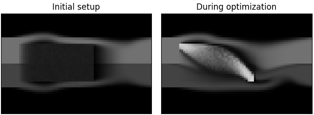
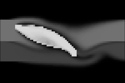
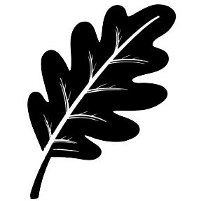
Sure enough, we get a beautiful little wing. Of all possible shapes, this is the very best one for creating efficient lift in our wind tunnel. This wing is definitely a toy solution since our simulation is coarse and not especially accurate. However, after making a few simple improvements we would be able to design real airplane wings this way. We would just need to:
- Simulate in 3D instead of 2D
- Use a mesh parameterization instead of a grid
- Make the flow laminar and compressible
Aside from these improvements, the overall principle is much the same. In both cases, we write down some words and symbols, turn them into code, and then use the code to shape our wing.2 The fact that we can do all of this without ever building a physical wing makes it feel a bit like magic. But this process really works, for when we put these wings on airplanes and trust them with our lives, they carry us safely to our destinations.3 4
Just like the real wind tunnels of the twentieth century, these simulated wind tunnels need to go through lots of debugging before we can trust them. In fact, while building this demo we discovered a number of ways that things can go wrong. Here are some of the most amusing failure cases:
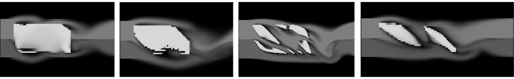
Several of these wings are just plain dreadful. But others seem reasonable, if unexpected. The two-wing solution is particularly amusing. We did not intend for this “biplane” solution to occur, and yet it is a completely viable way of solving the objective we wrote down. One advantage to keeping the problem setup so simple is that, in doing so, we left space for these surprising behaviors to occur.
The Manifold of Solutions
There are variations on the base wing shape which excel in particular niches. Sometimes we will want a wing that is optimal at high speeds and other times we will want one that is optimal at low speeds. In order to accommodate a large fuselage, we might want an extra-thick wing. Alternatively, in order to reduce its overall weight, we might want to keep it thin. It turns out that we can change simulation parameters and add auxiliary losses to find optimal wing shapes for each of these scenarios.
Our wind tunnel simulation is interesting first, because it illustrates how the Platonic ideal of wing design is rooted in the laws of physics. As we saw in the earlier posts, there were many cultural and technological forces that contributed to airfoil design. These forces were important for many reasons, but they were not the primary factor in the wing shapes they produced – physics was.
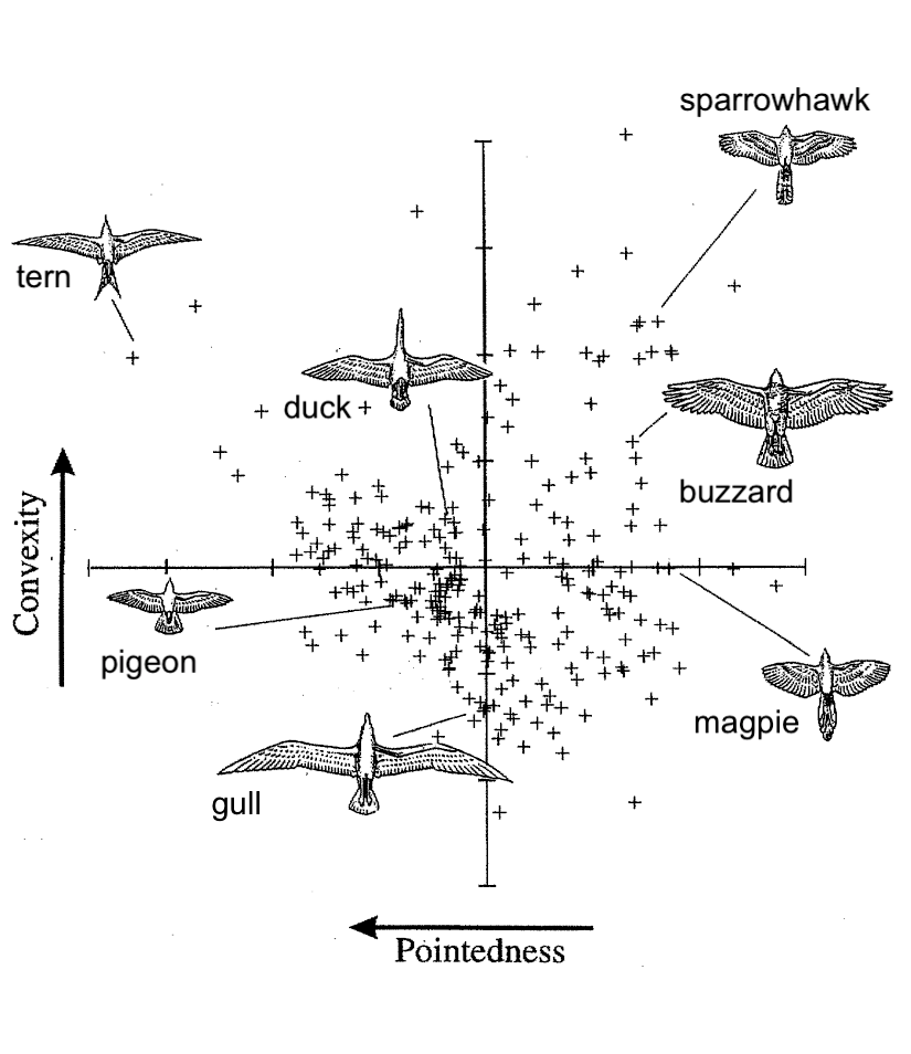
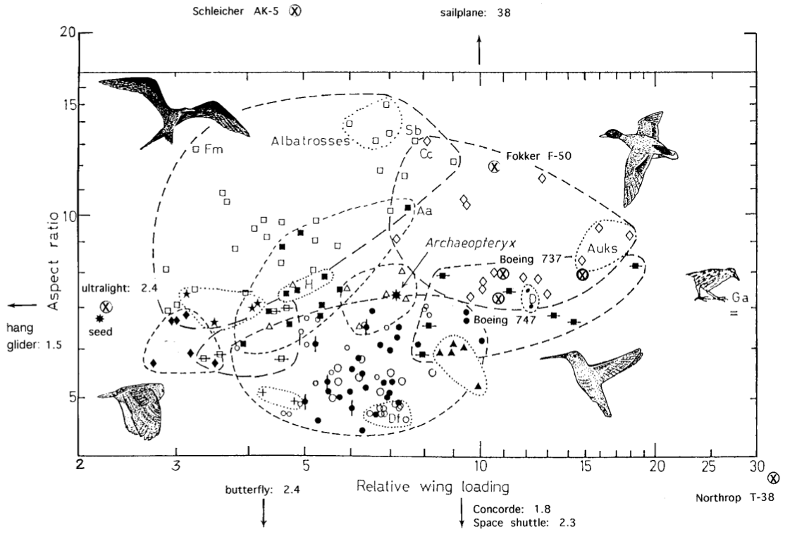
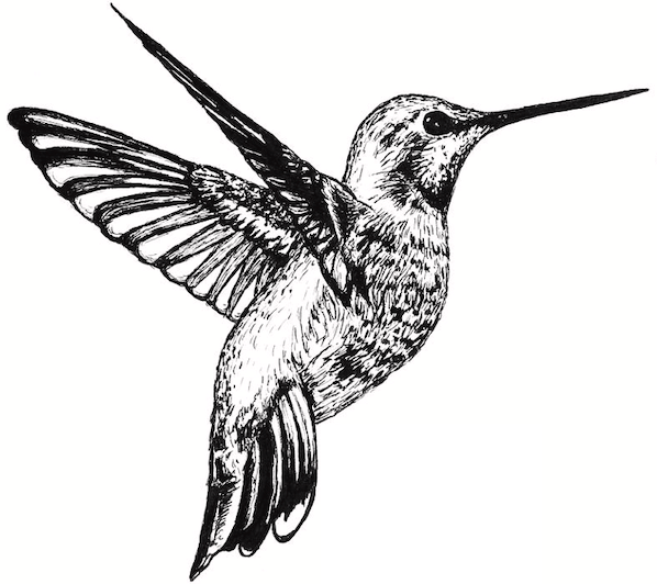
But to balance this idea, we have also shown how a million variants of the Platonic form of a wing can fulfill particular needs. Indeed, these variants could be said to occupy complimentary niches in the same way that different birds and flying insects occupy different niches in nature. After all, even though nature follows the laws of physics with absolute precision, she takes a consummate joy in variation. Look at the variety of wing shapes in birds, for example.5 Species of hummingbirds have wings with low aspect ratios that enable quick, agile flight patterns. Other birds, like the albatross, have high aspect ratios for extreme efficiency. Still others, like the common raven, are good all-around fliers. Remarkably, we are beginning to see this same speciation occur in modern aircraft as well. There are surveillance planes built for speed and stealth, short-winged bush planes built for maneuverability, and massive commercial airliners built for efficiency.6
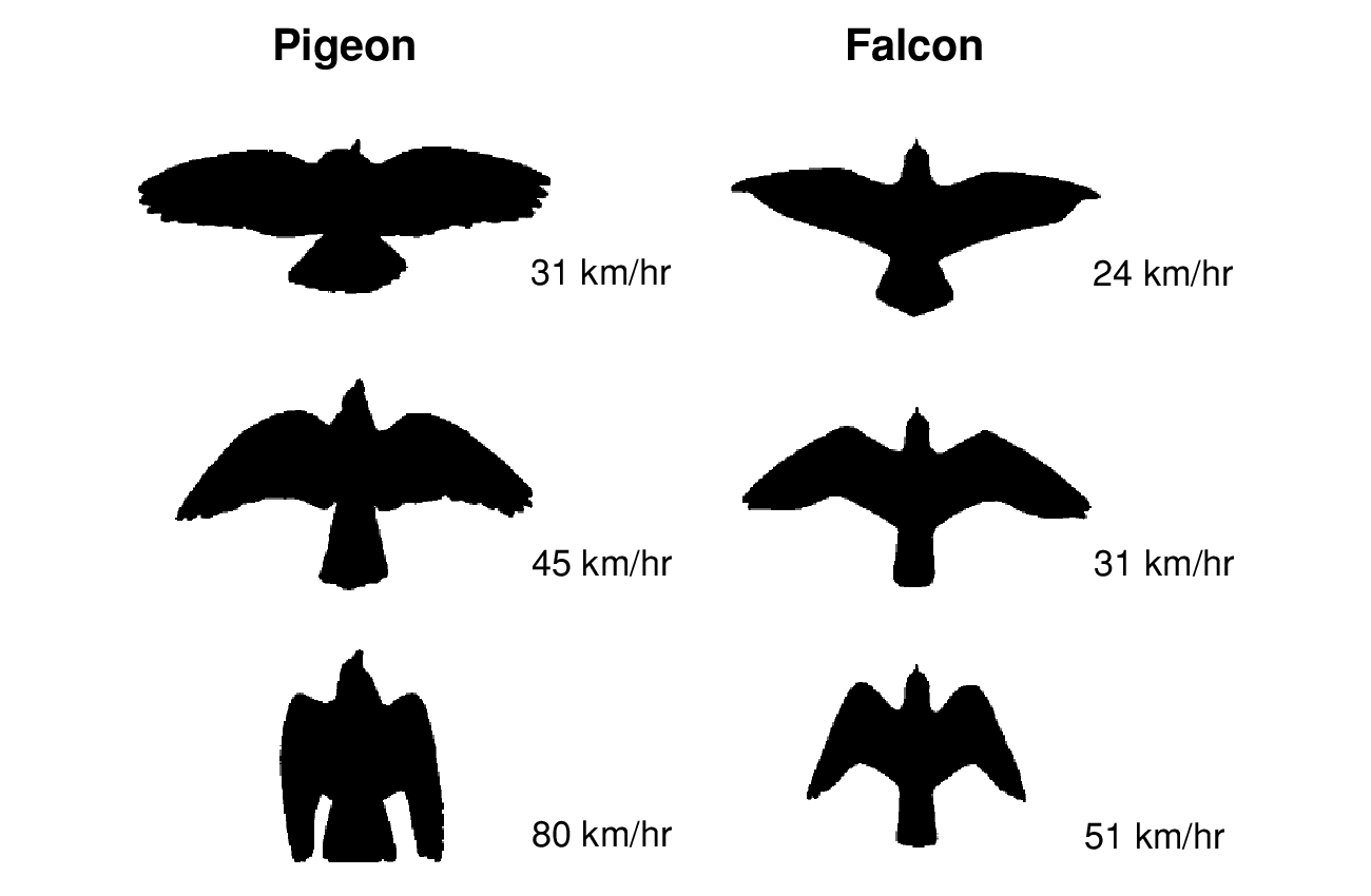
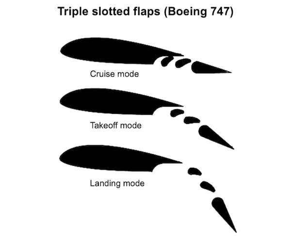
Perhaps less intuitively, even a single bird is capable of a huge range of wing shapes. The falcon, for example, uses different wing shapes for soaring, diving, turning, and landing. Its wings are not static things, but rather deformable, dynamic objects which are constantly adapting to their surroundings. And once again, we are beginning to see the same thing happen in modern aircrafts like the Boeing 747. The figure below shows how its triple-slotted wing design lets pilots reconfigure the airfoil shape during takeoff, cruising, and landing.
Closing Thoughts
One of the lessons from attempting to optimize a wing is that the optimization itself is never the full story. When we write down the optimization objective (like we did above), our minds already have a vague desire to obtain a wing. And behind that desire, our minds may want to obtain a wing because we are drawn to the technology of flight. And perhaps we are drawn to flight for the same reasons that the early aviators were – because it promises freedom, glory, and adventure. And behind those desires – what? The paradox of an objective function is that it always seems to have a deeper objective behind it.
The deeper objectives do not change as quickly. Even as the early aviators progressed from wingsuits to gliders to planes, they retained the same fundamental desire to fly. Their specific desires, of course, were different: some wanted to survive a tower jump and others wanted to break the speed of sound. And their specific desires led to specific improvements in technology such as a better understanding of the Smeaton coefficient or a stable supercritical airfoil. Once they made these improvements, the next generation was able to use them to pursue more ambitious goals. But even as this cycle progressed, the more deeply-held desire to fly continued to inspire and unify their efforts.
Thanks
Thanks to Maclaurin et al. (2018) for releasing Autograd1 to the world along with a number of thought-provoking demos. Thanks to Stephan Hoyer, Shan Carter, and Matthew Johnson for conversations that shaped some of the early versions of this work. And thanks to Andrew Sosanya, Jason Yosinski, and Tina White for feedback on early versions of this essay. Special thanks to my family and friends for serving as guinea pigs for early iterations of this story.
Footnotes
-
Specifically, we build on ideas laid out in Maclaurin et al. (2018). ↩ ↩2
-
See this online textbook page for an overview of full-scale wing optimization techniques. ↩
-
Jameson, Antony and Vassberg, John. Computational fluid dynamics for aerodynamic design - Its current and future impact, American Institute of Aeronautics & Astronautics, 2012. ↩
-
Jameson, Antony. Airplane Design with Aerodynamic Shape Optimization, Commercial Aircraft Company of China, Shanghai, 2010. ↩
-
Lockwood, Rowan and Swaddle, John P. and Rayner, Jeremy M. V. Avian Wingtip Shape Reconsidered: Wingtip Shape Indices and Morphological Adaptations to Migration, Journal of Avian Biology Vol. 29, No. 3, pp. 273-292, 1998. ↩
-
Norberg, Ulla M. Lindhe. Structure, Form, and Function of Flight in Engineering and the Living World. Journal of Morphology, 2002. ↩